|
| |
Support
Â
|
Cadrail 10.3.0 Update October
22, 2020
This update is free to all registered Cadrail
10
users (you must have purchased version 10 previously ).
Scroll down for a list of new features.
Owners of Cadrail Vesion 9 and earlier can order a
low cost upgrade to Cadrail 10. See the How To
Order page for details.
To see what Cadrail version you have, click
Help - About on the Cadrail program menus.
If you have an earlier version of Cadrail 10
installed
you can use the
Automatic Update feature and don't need to download updates
yourself. To use Automatic Updates go to to Cadrail menu item
Options - Check for Updates (or the automatic update on startup
feature) to install the updates.
Cadrail operates on most versions of
Windows including Windows 10 (see system
requirements).
If you are purchasing
Cadrail for the first time:
You do not need to download and install these
updates! You will receive the latest version with your purchase.
After you install Cadrail on your system and start the application,
it will automatically check for any future updates.
New in Version
10.3.0, 10-22-20:
* Improved Manual: updated PDF Manual and Application Help file.
* Improved Optimize: added layer checking.
* Improved Cadrail version 8 drawing import conversion problems.
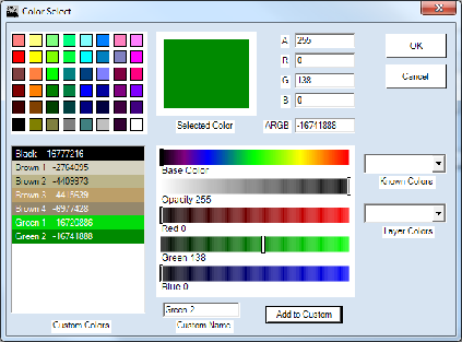
* Improved Color Dialog Custom Colors- if an existing custom color name
appears in custom color list that is the same as the dialog custom name
text box then when click add to custom colors button the existing color
will be changed to the current color settings on the dialog and saved
(was a new color was added to colors list with same name).
* Improved Printing: New print multiple documents option. When printing
multiple pages. Select multiple documents below the page row and columns
numeric up/down controls on the page setup tab of the print dialog. When
multi-document is selected a new document is created for each page
printed. Otherwise only one document is created that contains all the
pages printed (in previous versions of Cadrail a new document was
created for all pages only).
-option saved with the drawing print setup
* Improved Clone tool: (RMB Popup Toolbar) - Now works for Text Objects.
* Auto Update dialog resize problem corrected.
Â
Version
10.2.5, 5-25-19:
* Drawing Manager - Layer Treeview Improved.
Icom Icf4003 Programming Software Work [NEW]
How to Make Icom IC-F4003 Programming Software Work: A Complete Guide
Getting your Icom IC-F4003 two-way radio programmed correctly ensures your team has reliable, secure communications. However, setting up the cloning software and getting it to talk to your radio can sometimes be frustrating.
This comprehensive guide will walk you through exactly how to make the Icom IC-F4003 programming software work, clear up common compatibility issues, and resolve connection errors. 1. Gather the Required Correct Equipment
To program the IC-F4003, you cannot just use any software or cable. You need a specific hardware and software combination to establish a successful connection.
The Software: You need the Icom CS-F3001 cloning software. The IC-F4003 belongs to the IC-F3001/F4001 series, meaning they share the same utility program.
The Programming Cable: You need an OPC-478 (serial port) or OPC-478UC (USB port) cable.
The Adapter: The IC-F4003 uses a dual-pin jack (3.5mm and 2.5mm speaker/microphone port). Ensure your OPC-478 cable features the correct 3.5mm stereo plug connection designed for this radio series.
The Driver: If you use the OPC-478UC USB cable, you must install the specific PL2303 or FTDI USB-to-Serial driver provided by Icom. Without this, your computer will not recognize the cable. 2. Prepare Your PC Environment
Operating system mismatches are the primary reason programming software fails to work. Follow these steps to prepare your Windows PC: Install the USB Driver First
Never plug the USB programming cable into your computer before installing the driver. Download the official Icom UC driver pack. Run the installer as an Administrator.
Plug in your OPC-478UC cable only after the installation completes. Verify the COM Port Assignment
The Icom software looks for a specific communication (COM) port to talk to the radio.
Right-click the Windows Start button and open Device Manager . Expand the Ports (COM & LPT) section.
Look for "Prolific USB-to-Serial" or "Silicon Labs" and note the number next to it (e.g., COM3 ).
If the number is higher than COM4, right-click it, go to Properties > Port Settings > Advanced , and change it to an open port between COM1 and COM4 . The older Icom software handles lower COM port numbers much more reliably. 3. Step-by-Step Programming Process
Once your hardware and PC are configured, follow this sequence to read or write data to your IC-F4003. Connecting the Radio Ensure the IC-F4003 radio is turned OFF . Connect the OPC-478 cable to your computer's USB port.
Insert the 3.5mm jack firmly into the speaker/microphone jack on the side of the radio. (Ensure it clicks all the way in; a loose fit is a major cause of data failures). Turn the radio volume knob clockwise to power it ON . Running the CS-F3001 Software Launch the CS-F3001 software on your PC.
Click on COM Port in the top menu bar and select the exact COM port number you verified in the Device Manager.
Click on the Clone menu option, then click Read (Radio -> PC) .
A progress bar should appear, indicating the computer is downloading the current frequency configuration from the radio.
Note: Always save a backup copy of this original data file before making any changes. 4. Troubleshooting Common Software Errors
If your programming software is still not working, look out for these common issues: "No Answer from Transceiver" / "Connection Error" The Cause: The computer cannot see the radio.
The Fix: Check if the radio is turned on and the battery is fully charged. Inspect the 3.5mm plug on the side of the radio. Push it in firmly—dust covers or tight plastic housing can prevent the plug from seating properly. "Check COM Port" Error
The Cause: The software is targeting the wrong port, or the driver is broken.
The Fix: Re-verify your Device Manager. If you see a yellow exclamation mark next to your USB device, your driver is corrupted or Windows overrode it with an incompatible update. Roll back or reinstall the official Icom driver. Software Crashes on Windows 10 or Windows 11 The Cause: Legacy software compatibility issues.
The Fix: Right-click the CS-F3001 shortcut icon on your desktop, select Properties , go to the Compatibility tab, check "Run this program in compatibility mode for," and choose Windows 7 . Also, check the box at the bottom to Run this program as an administrator . 5. Best Practices for Modifying Frequencies
Once the software works and you can view your data channels, keep these guidelines in mind:
Frequency Range: The IC-F4003 is a UHF model operating between 400–470 MHz . Ensure you do not input frequencies outside this legal hardware limit.
RF Power Settings: You can toggle channels between High power (4W) for distance or Low power (1W) to save battery life.
CTCSS/DTCS Tones: If your team experiences static or interference from other radio users, utilize the Ch Setting table to program sub-audible analog (CTCSS) or digital (DTCS) squelch tones for privacy.
To help narrow down any remaining setup issues, please let me know:
What Windows operating system version are you currently running?
Are you using an original Icom cable or a third-party aftermarket cable? What specific error message is showing up on your screen?
I can provide step-by-step guidance tailored exactly to your current technical setup. Share public link
This public link is valid for 7 days and shares a thread, including any personal information you added. This link or copies made by others cannot be deleted. If you share with third parties, their policies apply. Can’t copy the link right now. Try again later.
To program an Icom IC-F4003 radio, you primarily need the CS-F3000 cloning software and a compatible programming cable. Although the software is named after the F3000 series, it is the official utility for both the IC-F3000 (VHF) and IC-F4000 (UHF) series, including the IC-F4003 model. Required Equipment
Software : The Icom CS-F3000 Programming Software is used to configure channel frequencies, privacy codes, and programmable key functions. Cable : The Go to product viewer dialog for this item.
(USB version) is the standard cable used to connect the radio to your PC.
PC : The software generally runs on Windows operating systems (Windows 7 through Windows 11). How the Programming Process Works
The software acts as a bridge between your computer and the radio, allowing you to manage the "black box" features in a readable layout. Connection : Connect the
cable to your PC's USB port and the radio’s speaker/microphone jack.
COM Port Setup : Ensure the correct COM port is selected in the software settings. If the radio isn't recognized, you may need to check the Device Manager on your PC to identify which port the USB cable is using. You can find COM port advice on enthusiast forums if you encounter connection errors.
Read Data : Use the "Clone -> Read" command to pull the current settings from the radio into the software. Editing : Modify channel information, including:
RX/TX Frequencies : Assign specific frequencies to each of the radio's channels.
CTCSS/DCS : Set privacy tones to filter out unwanted interference.
Function Keys : Customize what the side buttons do (e.g., Scan, Monitor, or High/Low power).
Write Data : Once changes are made, use the "Clone -> Write" command to upload the new configuration back to the radio. Troubleshooting & Tips
Understanding the Icom IC-F4003 Capabilities
Before diving into the programming process, it's helpful to understand the key specifications that make the IC-F4003 a popular choice. Operating in the UHF band (400–470 MHz), the radio provides excellent signal penetration and range for applications in industrial production, small and medium-sized businesses, tourism, transportation, and security. With a powerful 5W RF output and high/low power settings, it ensures reliable coverage in most working environments. Built to withstand harsh conditions, the IC-F4003 meets IP54 dust and water protection standards and passes 11 categories of MIL-STD-810 environmental tests. The radio features 16 programmable memory channels, each configurable with independent settings for frequency, power, and signaling like CTCSS and DTCS. Its 1500 mW loud audio output ensures clear communication even in noisy settings, while internal VOX capability allows for hands-free operation when paired with an optional headset.
The Right Programming Software: CS-F3000
The key to unlocking the IC-F4003's full potential lies in selecting the correct programming software. The official software for the IC-F4003 is the Icom CS-F3000 (version 1.10), despite the naming suggesting it is meant for the VHF series. The CS-F3000 software is universally compatible with all radios in the IC-F4000 UHF series, making it the right choice for the IC-F4003.
The official CS-F3000 software must be obtained from authorized dealers, as Icom does not offer its professional software for direct public download. While third-party software alternatives exist, using non-original software carries risks: unofficial or "cracked" versions can introduce malware, cause data corruption, or lead to improper frequency programming. The official CS-F3000 is a proprietary tool best acquired through a reputable dealer, such as Radiotronics UK.
Hardware Connection: OPC-478UC Programming Cable
To connect the IC-F4003 to a computer, you need the dedicated Icom OPC-478UC programming cable . This specific USB cable connects a PC's USB port to the radio's programming interface. The earlier OPC-478 serial cable, which required a computer with a legacy DB-9 serial port and proper COM port settings, is now rarely used.
Modern Windows PCs typically rely on the CH340/CH341 driver , which handles the USB-to-serial communication for many generic and OEM programming cables. It is essential to install the correct driver version for your operating system before connecting the radio to the PC.
Driver Installation and Troubleshooting
For the computer to communicate with the IC-F4003, the CH340 driver must be installed correctly. On modern Windows operating systems (10 and 11), the driver installation process is generally straightforward: plug the cable into a USB port, check Device Manager for the new COM port under "Ports (COM & LPT)", and if a yellow exclamation mark appears, manually install or update the driver. After installation, connect the radio while it is powered off, launch the CS-F3000 software, and select the appropriate COM port in the software settings before powering the radio on to avoid common communication errors.
Older versions of the CS-F3000 software are known to have compatibility issues with 64-bit versions of Windows. If the software fails to launch or crashes, you may need to run it in compatibility mode for an older version of Windows (such as Windows XP or Windows 7).
Step-by-Step Programming Process
Once the CS-F3000 software is installed and the radio is connected via the OPC-478UC cable with the CH340 driver properly configured, the programming process can begin. It is critical to first read the current data from the radio and back it up before making any changes, so you have a fallback option in case of any programming errors. The general process involves reading the radio's current data into the software, editing the parameters (frequency, power level, CTCSS/DTCS tones, and other advanced settings like 2-Tone or 5-Tone signaling), and then writing the modified data back to the radio.
Software Alternatives and Support
Several alternative programming solutions are worth considering. The RT Systems programming software offers a more user-friendly interface for specific radio models and automatically detects the USB cable and COM port, simplifying the setup process. However, RT Systems software is sold separately and requires the corresponding RT Systems USB cable for proper functionality. While many users inquire about CHIRP support for the IC-F4003, no official confirmation exists that the radio is supported by this free, open-source tool.
For further assistance, consider reaching out to the Icom Support Group on Facebook , a community managed with Radiotronics that provides a platform for users to share tips and ask questions. Alternatively, connecting with an Icom dealer or a professional radio system operator is often the most reliable way to get expert assistance, ensure proper frequency licensing, and avoid common mistakes.
Conclusion
Mastering the programming software is an essential skill for any user of the Icom IC-F4003. While the process requires the correct combination of hardware (the OPC-478UC cable), software (the official CS-F3000), and drivers (CH340/CH341), understanding the underlying workflow makes the task both manageable and rewarding. With its robust build quality, powerful audio, and versatile frequency range, a properly programmed Icom IC-F4003 radio is a communications tool that will serve your team reliably in the field for years to come.
Unlocking the Full Potential of the Icom ICF4003: A Comprehensive Guide to Programming Software
The Icom ICF4003 is a popular and versatile two-way radio that has been widely used by professionals and hobbyists alike. With its robust features and reliable performance, it's no wonder that many users want to customize and optimize their ICF4003 to suit their specific needs. This is where programming software comes in – a crucial tool that allows users to unlock the full potential of their radio. In this article, we'll delve into the world of Icom ICF4003 programming software and explore how it works.
What is Icom ICF4003 Programming Software?
Icom ICF4003 programming software is a specialized computer program designed to communicate with the ICF4003 radio. Its primary function is to allow users to modify and customize various settings, parameters, and features of the radio. This software enables users to access and adjust a wide range of settings, including frequencies, tone settings, squelch modes, and more.
Key Features of Icom ICF4003 Programming Software
The Icom ICF4003 programming software offers a range of features that make it an essential tool for radio enthusiasts. Some of the key features include: icom icf4003 programming software work
Memory Management : The software allows users to manage and edit the radio's memory channels, including adding, deleting, and modifying channel settings.
Frequency Programming : Users can program specific frequencies and settings for each channel, ensuring that the radio is optimized for their specific needs.
Tone and Squelch Settings : The software enables users to adjust tone and squelch settings, allowing for more precise control over the radio's reception and transmission.
Scan and Monitor Functions : Users can program the radio's scan and monitor functions, making it easier to monitor multiple channels and receive critical communications.
How Does Icom ICF4003 Programming Software Work?
The Icom ICF4003 programming software works by establishing a communication link between the radio and a computer. This is typically achieved through a programming cable that connects the radio to the computer's serial port or USB port. Once the connection is established, the software can access and modify the radio's settings and parameters.
The programming process typically involves the following steps:
Connecting the Radio to the Computer : The ICF4003 is connected to the computer using a programming cable.
Launching the Programming Software : The Icom ICF4003 programming software is launched on the computer.
Reading the Radio's Current Settings : The software reads the radio's current settings and parameters, allowing users to view and modify them.
Modifying Settings and Parameters : Users can modify various settings and parameters, such as frequencies, tone settings, and squelch modes.
Writing the New Settings to the Radio : Once the modifications are complete, the software writes the new settings to the radio. How to Make Icom IC-F4003 Programming Software Work:
Benefits of Using Icom ICF4003 Programming Software
The Icom ICF4003 programming software offers a range of benefits that make it an essential tool for radio enthusiasts. Some of the key benefits include:
Customization : The software allows users to customize their radio to suit their specific needs, ensuring optimal performance and functionality.
Increased Efficiency : By programming the radio's settings and parameters, users can streamline their communication processes and reduce errors.
Improved Performance : The software enables users to optimize the radio's performance, ensuring reliable and clear communication.
Common Applications of Icom ICF4003 Programming Software
The Icom ICF4003 programming software has a range of applications across various industries and use cases. Some of the most common applications include: The Software: You need the Icom CS-F3001 cloning software
Public Safety : Emergency responders and public safety agencies use the ICF4003 programming software to customize their radios for critical communication applications.
Commercial and Industrial : Businesses and organizations use the software to program their radios for specific applications, such as warehouse management or industrial operations.
Amateur Radio : Hobbyists and amateur radio enthusiasts use the software to customize their radios for personal use.
Conclusion
The Icom ICF4003 programming software is a powerful tool that unlocks the full potential of the ICF4003 radio. By providing users with a range of customization options and features, the software enables optimal performance and functionality. Whether you're a professional user or a hobbyist, the Icom ICF4003 programming software is an essential tool that can help you get the most out of your radio. With its ease of use and versatility, it's no wonder that this software has become a staple in the world of two-way radio communication.
* New Select Multiple: similar to Select in
Rectangle (Ctrl+ or none) and Polygon (Alt+).
-
Press Ctrl+Alt keys when clicking the
Left Mouse Button (LMB) to select individual objects in a temp list.
-
Makes temp figure that can then be manipulated
with figure tools.
-
Click Ctrl+Alt again on an object already
selected to remove it from the selected temp figure objects.
* New Borderless Form Option on Cadrail
menu: Options - Preferences - Setup Tab. The borderless form
style used in previous versions of Cadrail 10 disables some windows
features. The affected features (other than cosmetic) involve multiple
monitors and application resizing. If you wish to restore the features
turn off the Borderless Form option. When the Cadrail is (or update) is
first installed the Borderless Form Option is OFF by default.
Optional Borderless Form and Metro
Colors.
* Corrected problem selecting objects stacked with
dimensions objects in same space.
* Corrected problem saving startup position
settings on secondary monitors.
* Color dialog opacity for all colors can be used
for terrain, track road base etc.
* Symbols Trees allow edit styles in Drawing menu
Object Data.
* Phantom line style is highlighted by auto find in
plan view and when selected.
Documentation
Updates
| Select in Rectangle Fence
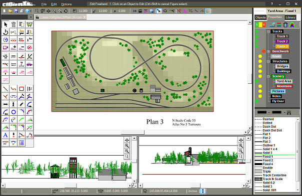
Method 1: Press the Left Mouse Button (LMB) down and drag
to create the rectangle. If no object is found where clicked the
rectangle is begun. If an object is found it will be selected.
Method 2: Press Ctrl Key + LMB down and drag. A rectangle
is begun from the clicked point (weather object is there or
not). Once the Rectangle is defined the objects totally
enclosed within the fence will be selected into a temporary
Figure group. If any Object in a Figure is selected, the entire
Figure will be selected. After selecting object other tools
such as Freehand Move, Delete, Copy, etc can be applied to the
temporary Figure. |
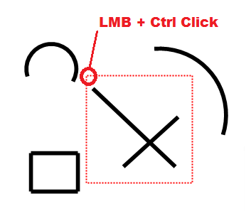 |
| Select in Polygon Fence Press
the Alt Key + LMB, move the mouse to a second point to
create a Line and click again (no key press required). Continue
clicking to create a polygon fence surrounding the objects you
want to select.
After the Polygon is complete click the RMB to close
the fence and select the enclosed objects.
|
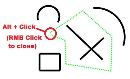 |
| Select Multiple Objects Press
the Ctrl+Alt+LMB on an object to select it in a multiple
object Figure group. Continue Ctrl+Alt+LMB Clicking other
objects to add them to the Figure.
Ctrl+Alt+LMB Click a selected object again to de-select it. |
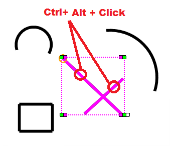 |
Selecting Groups of Objects 3 ways.
Mouse + Keypress Combinations
Mouse
Button |
Key+ |
Description |
| Â |
 |
 |
| LMB |
 |
 |
| Â |
none |
Edit Freehand: select in rectangle
fence. Fence begins when  no object is clicked. |
| Â |
shift |
Get End, Get Object. |
| Â |
ctrl |
Select in rectangle fence (Edit Freehand or
CAD tools). Fence begins at click point whether object is found
or not.
Trim object option for some tools.
|
| Â |
shift+ctrl |
Select single object in a Figure
|
| Â |
alt |
Click to Select in Polygon Fence. Press
Alt+ Click
first point, continue clicking points to create the lines of the
polygon (Pressing alt+ is optional for remaining click points in
polygon).
|
| Â |
ctrl+alt |
Click to Select Multiple Objects. When an object is
found at the click point a temporary list of Objects (Figure
group) is begun. Continue Clicking objects while pressing
Ctrl+Alt for each object clicked. To remove an object simply
click it again while pressing Ctrl+Alt.
|
| Â |
 |
 |
| RMB |
 |
 |
| Â |
none |
Click to Show RMB Popup.
Click to Close Select in Polygon Fence (when active).
Drag RMB to scroll Drawing Screen.
|
| Â |
shift |
Show RMB Popup with selected object if
found.
|
| Â |
ctrl |
Move Drawing Toolbar to Click location. If
a tool is immediately selected the toolbar snaps back to upper
left.
|
| Â |
 |
 |
| Â |
 |
LMB = Left Mouse ButtonÂ
RMB = Right Mouse Button |
Mouse keypress combinations summary.
|
|
 |
|
 |
Version 10.2.4 Update
March 18, 2019
* New: Select in Polygon
Fence
- Similar to Rectangle
Fence.
- Press Alt+ key with
Mouse click on first point to make a selection fence with multiple
lines.
- RMB to stop fence and
make temp fig of objects totally enclosed in fence.
- Figures that are
partially selected in fence are totally selected in new figure.
* Improved: Color Dialog
- Add custom color
descriptions, unlimited number of colors.
- RMB for popup menu:
delete, rename.
- Drag and drop order of colors in the list.
- Opacity setting with
all colors and any object ie object body, fills, layers, etc. (was
option for figure fills only).
- Select from layer
colors on color dialog.
* Drawing: corrected problem with size
tool and full circles changing pc, pt points wrong.
- To correct in existing
drawings use Options-optimize in the new version.
* Auto Update: corrected auto update
problem for some language settings
* Printing: corrected problem border = 0
was not saved with the drawing.
Version 10.2.2 December 22, 2017
* File Save: corrected problem some large drawings very slow (10.2.1
only). Only does new quick optimize during save as (was save and save
as). Much faster now.
* Optimize: additional checking for drawing corruption from past versions.
Improved speed.
* Runrail: corrected problem adding cars (10.2.1 only).
* GetEnd: corrected problem when Snap is on.
* Save Picture: increased maximum picture width to 8000 pixels (was 4000). If
you get an out of memory error on your system then you need to do smaller sizes.
* Other minor corrections and improvements.
Version 10.2.1 November 21, 2017
* New Look: The main Cadrail
Application style has been changed slightly. Now Cadrail has a flat
borderless Windows 10 appearance (in Windows 7 and XP). We have
arranged the toolbars more compactly and removed duplicate
functions. So in a way nothing has changed
Cadrail is just more compact.
Â
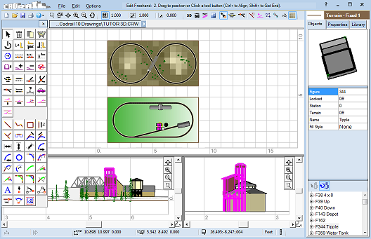
Cadrail version 10.2 application
window.
Duplicate functions removed:
-
Main menu item View removed. The View is
more easily set
using the Mouse Wheel Zoom and RMB Drag Screen. Old dialog
still available on bottom toolbar. Hot keys F2-F9 are still
active.
-
Main menu item Help removed. Use top tool
buttons upper left.
F1 Hot key still active. RMB click controls for individual tool
help.
-
Top toolbar Layer/Style Properties fly
out
toolbar removed.
Use Drawing Manager Properties Tab.
-
Auto-Select tool removed. Proved
more confusing than useful.
Â
* Improved Performance:
General optimization improves performance.
* New 3d:
-
Figures are filled in a fan pattern
around the polygon, 3 and 4 side figures will show a single
image fill. More than 4 sides repeat the image in a triangle
fan pattern.
Â
-
Filled figures: when the fig is a
rectangle with picture fill, must define fig objects
starting with bottom of rect (in relation to picture bottom
y axis in plan view) and define fig objects clockwise. ie
bottom, left, top, right.
Â
-
Changing the order and direction will
change the picture orientation in the 3d view. So that can
be used if thats what you want ie flip or rotate the
picture. Otherwise define the figure starting at lowest y
value (bottom) in the plan view and add objects to the
figure clockwise.
Â
-
Optional tile property for texture
picture filled figures.
Â
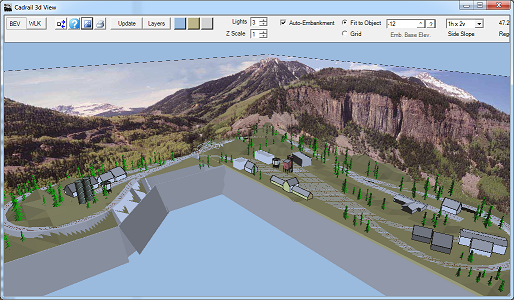
3d view with photo
backgrounds.
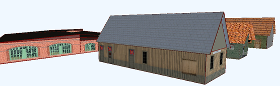
Buildings with 3d photo
textures.
-
Lights improved: choose from 0 to 3
lights using numericupdown control located on the 3d view top
toolbar where the Lights button was previously.
Â
-
Auto-Embankment Improved with a New
Embankment Option (3d view top tool bar).
Â
FIT TO OBJECT produces much more
accurate embankments. Each object is now closely fit by the
embankment following curves and angles. Previously the
embankment used a square grid which made jagged edges.
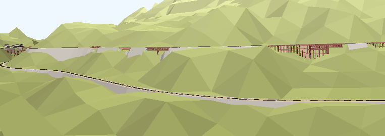
Fit to Object Embankment
The previous embankment method is still available as the
GRID option. You can switch back and forth between
methods.
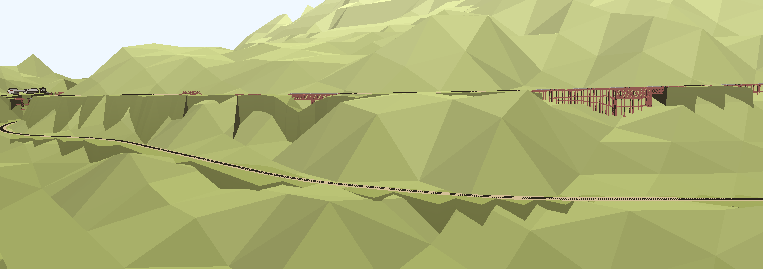
Grid Embankment
In some cases the drawings that depend on the old
auto-terrain methods using contours and etc don't work well
with the new Fit to Object option. Use the grid option for
backward compatibility. This older technique for terrain is
no longer required as the Figure Terrain Fill is much better
for producing landscape terrain like mountains. This allows
the new 3d view Auto-Embankment to be much more precise.
The new Fit to Object embankment lets you set the desired
side slope using the slope drop down list on the 3d top
toolbar. Plus you can set the embankment color for the Fit
to Object option using the embankment color button on
the 3d top toolbar.
Â
* New Cadrail Application Color Options:
options-preferences setup tab select from choices on the drop down
list
Â
* New Copy/Paste to Clipboard buttons on
RMB Popup Toolbar (was only Edit Menu).
* Undo improved: the way Cadrail stores Undo info in memory has been changed.
The new way will help minimize application memory usage. Plus all
functions can now be undone.
-
Faster for large drawings, more reliable.
Â
-
Limited number of undo set in menu Options
- Preferences - Setup Tab.
Â
-
Undos reset when changing drawing tabs.
Â
-
New undos: object front/back, edit
layers/styles, optimize drawing.
Â
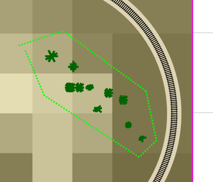
* New: Figure Fill Terrain: New Symbols to
Terrain button on the Terrain toolbar sets all symbols (like
trees) over the selected terrain to the terrain elevation. This
feature is also available with the Elevate tool on the Drawing
Toolbar.
* Side View, Horizontal and Vertical splitter
positions saved with Cadrail settings.
* Pictures new size limit: The maximum width or
height for an original image is 5000 pixels. If you attempt to
insert picture larger than 5000 pixels it will be resized to 5000
pixels in the drawing (which is then fit to the picture drawing
scale width).
* Optimized: Several basic functions have been
optimized to improve speed and memory usage.
* Application Help and Manual have been updated.
* Basic system requirements have not changed
from 10.1. Version 10.0 and 10.1 will read the 10.2 drawings but do
not show new features: images in 3d, new Fit to Object embankment.
All other features are the same between versions.
* 10.2 drawing files are backward compatible with
earlier Cadrail 10 versions. However the previous versions do not show
the new features.
Â
|
 If you have an earlier version of Cadrail 10 installed
you canÂ
use the Automatic Update feature  to install the newest
version. You should be notified to download the update when you start
Cadrail if the Auto-Update feature is on.
See the new Sample Drawings for more
examples.
|
 |
|
 Version 10.1.1 February 22, 2017
Summary
The next time you start Cadrail 10.0 you will be notified that the newest version of Cadrail
is now available!
In Cadrail Version 10.1 you will find major improvements
that focus on simplifying all data entry and object editing tools.
We have also improved the basic graphics animation when moving objects on
the screen. The drawing is smoother with less updating.
Auto-find has been greatly improved to identify only those objects valid for
a specific tool. For example when using the Line Freehand tool, no
Auto-Find objects are highlighted until you press the shift key for get
end or select object. Only valid
objects are highlighted for the tool. The valid objects will be highlighted
and the selected end point shown. For tools like Line Freehand, when over a
Figure, only the single objects are highlighted not the figure.
Auto-Find
is one of the most used features for drawing.
Ease of editing tools extend to the updated Object Data Grid (ODG)
and Figures Treeview on the Drawing Manager. Now you can edit Object
Properties in the Object Data Grid (ODG) by clicking the right column value. All
the features that were once found through the previous Object,
Figure, and Text editor dialogs are now directly available in the
Object Data Grid and Figures Treeview. In addition there are new RMB Popup
Menus with additional features for the ODG, Treeview, Layers,
Styles.
Easily edit Figures by dragging and dropping objects within the
Drawing Manager Figure Treeview (below the Object Data Grid). Just
arrange the objects and figures in the combinations and order you
desire by dragging and dropping the objects in the Treeview. New RMB
Popup Menu with additional features.
Â
Now numeric values may be entered in place without using the Input
Dialog. Instead you may now edit or input the value directly into
its display text box for the appropriate tool. For example to change
the Grid increment, click the Increment display and edit the value. New number
formatting has been incorporated to let you more easily specify feet
inches fraction and other formats.
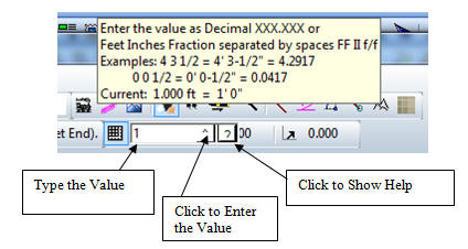
New Direct Numeric Input and Formatting
Â
There is a new Input Toolbar (was Input
Dialog) that incorporates the improved numeric text box for entering
multiple values with tools like Enter Coordinates on the bottom
toolbar. Enter the values using the new feet-inches format as
desired.
All of Cadrail's toolbars and dialogs have been updated with the new
numeric input text box.
Text objects are now edited in place in the drawing by double
clicking the text object and selecting the options on the new text
edit toolbar that pops up.
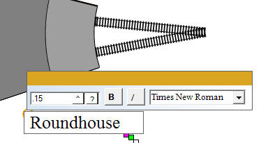
New Text Input and Toolbar
A new "Smart" toolbar replaces the previous popup menu
when clicking the Right Mouse Button (RMB) in the Plan View drawing
area. The new RMB Popup Toolbar gives
you the most used tools and the tool buttons shown are targeted for your need based on
the
tools and objects selected when you click for the toolbar.
You can also edit object properties directly on the toolbar using an Object
Data Grid.
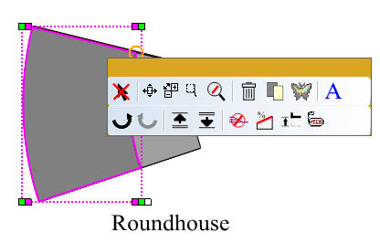
New RMB Popup Toolbar
The Help Documents and Manual have been updated for 10.1. You can
now RMB click any control on the main application window and content
specific help pops up.
Many more improvements are listed below.
|
Â
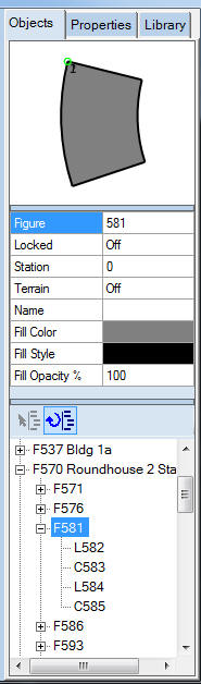
New: Drag and Drop Objects in the Tree View.
New: Edit Object Properties in the Object Data Grid. Change
Layers, Grades, Angles, etc.
|
 |
10.1.1Â 2-22-17
* Compiled with newest Microsoft technology. Application requirements have not
changed. Operates on Windows versions XP, Vista, 7, 8, 10.
* Improved Graphics: Drawing
tool animation for moving and object tracers is now smoother with
less blinking of the screen. Too many changes to describe. Many you
may not notice unless you run the old versions to compare.
* New Help: All documents
updated for version 10.1 (Help, PDF, Manual). New Right Mouse Button
(RMB) help for all Main Application toolbar buttons.
* Improved: Autofind
Highlights have been incorporated for each specific tool. For
example when using the Line Freehand tool, press the Shift key for
Get End and Autofind will highlight valid object endpoints you can
click.
* New Text: Edit text in the
drawing plan view. A new text entry box and font selection toolbar
is shown by: creating text, double clicking existing text in the
drawing area, or by selecting Edit Text on the drawing area RMB
PopUp toolbar. All text properties can also be changed using the
Drawing Manager Object Data Grid.
* New Input Number Box - All
tools that require a numeric value like grid, snap, ortho,
dimensions, Object Data etc. now use an in place text edit box.
Previously the Input dialog was used to enter numbers.
This edit in place text box simplifies number entry by eliminating
the old Input Dialog. This feature has been implemented throughout
Cadrail any time a number is entered.
- After clicking a value display a text box appears where you
may enter the value in place (previously the Input Dialog would
appear).
- Input Decimal value or feet inches fraction, for angles
enter decimal or deg min sec (separated by spaces).
- Click ^ button to enter the value (or press Enter key).
- Click ? button to pop up help display
- Press Esc key to cancel
* New Object Editing - now built
into the Drawing Manager - Object Data Grid (ODG) and Drawing
Treeview. The old Object Editor dialogs have all been replaced
by editing and selecting options in the Object Data Grid cells. This
greatly simplifies entering and editing object data.
Â
- Select object using Freehand Edit tool and the object data
will be shown in the Drawing Manager- Objects Tab.
- Click the right column of the Object Data Grid to select the
value cell you wish to edit.
- Click again to begin editing.
- For numeric or text editing, click away from the cell on
some other area of the object data grid to save the value and
complete the operation (optionally press the <Enter> key. Press
the <esc> key to cancel editing without changing the cell value.
- The grid cells use a new format to enter feet/inches
introduced with the new Input number box (see above).
- Properties adjust as editing ie change circle length the
delta changes.
- Figures or objects - double click sta for profile (was sta
elev dialog) or select profile from RMB menu.
- Double click Layer or Style in left column for edit Layers
or Styles dialogs.
- Combine use with drawing Figures Treeview to edit objects
and figures
- Object Data Grid also found on RMB popup menu
- Picture Paint dialog (was Picture Edit on Object Editor)
moved to RMB pop up menu or toolbar.
- Edit figure object order using the new drag/drop
capabilities of the Drawing Figures Treeview below the Object
Data display. Use
the Drawing Treeview RMB pop up menu for additional figure
options.
- Tool tip help shows feet-inch-fraction for numeric values.
* New: Drawing Figures Tree View
(DM Objects Tab)
- New drag and drop to reorder objects and figures.
- RMB popup menu - undo, delete, send front/back, fill child
Figures, picture paint, etc.
- Drag and drop Figures to drawing (unchanged)
* New Drawing Area RMB PopUp Toolbar
with Targeted Tools related to selected object. Replaces previous
RMB cancel menu.
- If an object has been selected in the Plan View with Edit
Freehand, the RMB Popup Toolbar will have additional buttons
with tools specific to the selected item type.
- Common items Edit Freehand, Zoom, Figures, Copy, Delete,
etc.
- New Last Tool - sets to the previously selected tool.
- New buttons to activate Text Edit toolbar, Terrain toolbar,
Profile Dialog, Picture Paint.
- New Clone Properties - sets the properties toolbars
to the selected object's layer and style.
- New Edit Object button shows ODG below RMB Popup
Toolbar.
- New Shift+RMB click to select object and show Popup Toolbar.
* New:Â Profile Dialog
(was Station Elevation dialog)
- Now works with single objects line, circle, spiral (was just
Figs).
- Access with RMB popup toolbar on drawing window, object data
grid RMB menu, or drawing tree RMB menu.
- More saved custom dialog settings.
- Eliminated station ON option. Now the initial station value
is zero for
all objects. When a station value has been entered the value is
added at each endpoint. The station is shown on the screen when
the Stations-Elevations labels option is on and the Station
value is greater than zero.
Â
* New: 3d View
- New Background Color button on 3d view toolbar next to
terrain color.
Click the button and the color you select from the Color dialog
is shown in the 3d background.
- New: Open 3d View using new 3d View button on main Top
Toolbar next to the Runrail button.
- New: use Shift+ mouse button for 20 percent slower screen
scrolling.
* New Figures- Solid Fill -
New Fill Opacity Property. Enter value 1 to 100 percent for fill
transparency. 1 is totally transparent 100 is none or solid fill
color.
* New Dimension: Edit font name,
bold, italic by object with Object Data View.
* New Styles Editor: Move
Styles button allows you to select two styles in the list and the
objects with the second style are changed to the first selected
style.
* New Pan Screen: Now use either
RMB or CMW to drag or pan the screen. The previous Pan Screen button
has been removed. The RMB Popup Toolbar still activates when the
drawing area is clicked without dragging or moving the mouse. To pan
the screen, press the RMB down and drag the screen while holding the
RMB down.
* New Preview on DM Objects
Tab size is now adjustable with new splitter bar, saved with
settings.
* New: Scrollbars show/hide
button on bottom toolbar right.
* New: Side View the Lines show
thickness Z axis dimension.
* New: Edit Terrain, Edit Text:
Activate editing in place toolbars by double clicking object in the
drawing area or by selecting Edit on the RMB popup menu (after
selecting the object in the drawing area).
* New Terrain Toolbar:
Elevations option. Shows elevations at all times not just when
terrain selected. - drag header to move toolbar
* New: Elevate tool - Option to
set symbols to terrain elev. When Terrain is elevated the change is
added to all terrain grid elevations.
* New: Print dialog- added rmb
drag preview, cmw zoom.
* Import DXF
- Corrected problem with some layer settings that would cause
an error and not read the file.
- Corrected problem of layers as children of layer 0, now all
imported layers are main level parents.
- Corrected problems export spirals
* File Open, Import: Merge 9,
10, Optimized. Improved cleanup of corrupt drawings.
* Shape Builder: Yard Ladder -
corrected problem with some near vertical lines. Other problems Yard
Builder.
* Changed: If the Cadrail Window is minimized
on exit the window is
restored to normal size and then saved. This avoids confusion when
Cadrail starts minimized.
* Changed Phantom Style: Now this
style is not drawn in both Plan View and 3d View (was only 3d view).
This allows objects like Figure Terrain to show only the fill.
* Main Menu (File, View...) Text size corrected for video
settings 125, 150 dpi (control panel).
Â
_______________________________________________
Version 10.0.2 September 14, 2015
* New: Symbols Objects.

New Symbols
Toolbar.
- Now instead of a single point object you can select different
symbols from the pop up toolbar.
- Select round, square, flag or other symbols.
- At this time the symbols are basically flags and trees. Although
the circles could be anything.
- All tools work normally for symbols. You can size, rotate,
layers, styles.
- The Interior symbol pattern can not be edited.
- Symbols are light weight objects meant to reduce the drawing
overhead for objects that are repeated many times in a drawing, like
trees.
- Symbols are easier to use than Figures but the symbol itself is
not user editable.
- There are six basic groups of tree symbols. Each group has 1 to
5 levels of "branches". The tree symbols are also shown in the Side
and 3d views.
- To draw a flag or tree symbol:
1. Click the symbol type on the symbol toolbar (the toolbar appears
when you select the Symbol - Freehand tool on the drawing toolbar).
2. Press down the left mouse button at the symbol radius point.
3. While holding the mouse down, drag the mouse to select the
size and angle for the symbol.
Â
4. Release the mouse when the desired result is shown.
Â
- The round and square point symbols operate as just a single
point with no size as before.
- When a symbol is created or moved onto terrain it is assigned
the terrain elevation. If you change the terrain elevation the
symbol elevation is changed. To change an existing symbol to fit the
terrain you just move the symbol. If the terrain or symbol layer is
frozen or off then it will not change.
- The symbols are compatible in earlier versions but appear as a
standard point only
Â
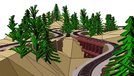
Layout 9
demonstrates Symbol trees and Figure Terrain.
* New Figure Terrain:
- Terrain Show/Hide button on the Labels tool bar allows the
terrain figure colored background grid to be drawn at all times in
the plan view (was just when terrain figure was selected). When the
terrain figure is selected the grid toolbar, lines, and elevations
are drawn. This setting is saved with the drawing.
- New: Elevate tool now adjusts the terrain grid elevations and
the terrain border objects.
- New: Auto-Color for plan view Terrain is based on the color set
for the 3d view Auto-Terrain on the 3d view toolbar.
* NEW File - Export - Export as Cadrail 9.53
- Saves the current drawing in Cadrail 9.53 format (any version 9
or 10 will read it).
- Things that are new in V10 (pictures, terrain) will not appear
in the 9.53 drawing.
- Layers are reorganized for 9.53 to remove the Parent/Child from
v10. Visible/freeze may need to be set after conversion from 10.
- When the version 10 file is saved as 9.53 any Terrain or
Pictures are removed. Any Symbols are changed to a point.
* File – Import – Merge Improved: Now you can use shift+, and
ctrl+ to select multiple files in the dialog file list. All the
selected drawings
will be merged into the current Cadrail drawing. Merge version 9 or 10.
* Save Picture in Fence: Corrected problem with save as .WMF .
* Select in Fence tool: corrected problems when object within fence is
already part of an existing figure. Now the entire figure is added to
the fence objects even if outside the fence. This duplicates the create
figure tool behavior and prevents single objects from being defined in
two different figures.
* 3d view:
- Changed Auto-Terrain color from drop down list of four colors to
any color selected on the color dialog. Light Brown is the default
color. This color setting is also used for the Figure-Terrain
Auto-Color value in the plan view. This color is automatically
varied from light to dark based on the elevation. The adjustable
color requires 10.0.2.
- Additional adjustments to 3d view color, auto-terrain.
* Extend tool - extend arc to end of arc with same radius pointt
corrected.
* Arc project tool - project arc to end of arc with same radius
pointt corrected.
* Dimension tool - corrected fractions option when drawing preference
units inches.
* Corrected problem creating new drawings when opening/closing
multiple drawings.
* Misc other corrections to converting and optimizing drawings.
* New Sample plans using Tree Symbols and
Figure Terrain...
_______________________________________________
Version 10.0.1 April 4, 2015
* New Picture Editor:
- Activate from Picture Editor button on Object Editor dialog,
change brightness, gamma, opacity, RGB.
* Stations & Elevations Dialog improved:
- Added Table of values.
- Acess by double clicking station on/off value in the object
data list.
on the drawing manager or using figure editor button.
- Zoom view.
- Print profile and data table.
* 3d cab view high low option:
- Low view is closest to engineers true view in the cab.
- High view allows view to rear of train over cab.
* Dimension - fraction option:
- Corrected rounding errors.
- Corrected problem editing the text in object editor.
* Divide into Segments tool: corrected problem
generating error message with Auto-Find.
* Drawing Tabs: moved close button onto tab (was far
right).
* File Open: corrected problem when opening a fifth
drawing.
* Layer Tree:
- Now set by clicking the position of visible,
freeze, off in any order. Was click entire button to
cycle v, f, o in order.
- Improved drag and drop highlight.
- Corrected problem if drag and drop layer on
itself disappears.
* Rotate, Flip tools: corrected problems with
rotation point.
* Optimize Drawing: added additional checking for
invalid objects, use to remove zero or infinite
objects.
* Text - improved clarity, less bold |
|
 |
|
_______________________________________________
Â
What's new in Cadrail Version 10.0.0 ...
Whats new in Cadrail Version 9.0 ...
|
|